Fill Out Your Megger Test Template
Fill Out Your Megger Test Template
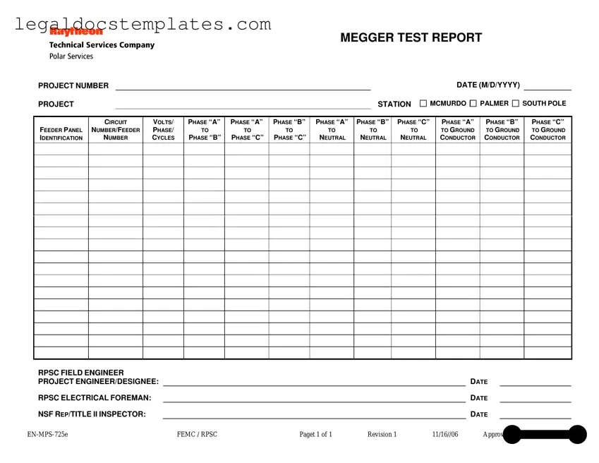
In the realm of electrical safety and maintenance, comprehensive and detailed documentation is crucial. Among such essential documents is the Megger Test form, a standardized report that professionals widely use to record the results of insulation resistance tests. This form plays an instrumental role in ensuring electrical systems are maintained at optimal safety levels. It meticulously captures vital information, including the project number, project station with designated places like McMurdo, Palmer, and South Pole, and the date of the testing. Furthermore, it details specifics of the electrical circuitry under examination, such as feeder panel identification, circuit or feeder number, along with the voltage, phase, and cycles. The form is designed to record measurements between various phases to each other, phases to neutral, and phases to ground conductors, providing a comprehensive view of the electrical system's insulation status. Approved by Wayne L. Cornell, this document also includes sections for the RPSC Field Engineer, Project Engineer/Designee, RPSC Electrical Foreman, and NSF Representative/Title II Inspector to sign off on the test, ensuring that all relevant parties are informed of the test results. The Megger Test form, with its structured approach to documenting insulation resistance measurements, is an indispensable tool for electrical safety and maintenance protocols.
MEGGER TEST REPORT
PROJECT NUMBER
PROJECT |
|
STATION |
DATE (M/D/YYYY)
MCMURDO 
 PALMER
 SOUTH POLE
FEEDER PANEL IDENTIFICATION
CIRCUIT
NUMBER/FEEDER
NUMBER
VOLTS/
PHASE/
CYCLES
PHASE “A”
TO
PHASE “B”
PHASE “A”
TO
PHASE “C”
PHASE “B”
TO
PHASE “C”
PHASE “A”
TO
NEUTRAL
PHASE “B”
TO
NEUTRAL
PHASE “C”
TO
NEUTRAL
PHASE “A”
TO GROUND CONDUCTOR
PHASE “B”
TO GROUND CONDUCTOR
PHASE “C”
TO GROUND CONDUCTOR
RPSC FIELD ENGINEER |
|
|
|
|
|
|
PROJECT ENGINEER/DESIGNEE: |
|
|
|
|
DATE |
|
RPSC ELECTRICAL FOREMAN: |
|
|
|
|
DATE |
|
NSF REP/TITLE II INSPECTOR: |
|
|
|
|
DATE |
|
FEMC / RPSC |
Paget 1 of 1 |
Revision 1 |
11/16//06 |
Approved by Wayne L. Cornell |
||
| Fact Name | Description |
|---|---|
| Document Title | Megger Test Report |
| Purpose | Used to record insulation resistance measurements of electrical circuits |
| Key Information Required | Project number, station, test date, feeder panel identification, circuit/feeder number, volts/phase/cycles, and resistance measurements between phases, to neutral, and to ground. |
| Specific Stations | McMurdo, Palmer, and South Pole are mentioned, indicating use in polar regions. |
| Approval Date | Revision approved on November 16, 2006 |
| Approval Authority | Approved by Wayne L. Cornell |
| Governing Law(s) | No specific state law mentioned; however, as an Antarctic operation, it may be governed by federal and international agreements relevant to Antarctic operations. |
| Roles Involved | Includes roles for RPSC Field Engineer, Project Engineer/Designee, RPSC Electrical Foreman, and NSF Rep/Title II Inspector. |
| Document Identification | Identified as EN-MPS-725e FEMC / RPSC, Page 1 of 1, Revision 1. |
After completing a Megger Test, which measures the insulation resistance of electrical wires, the next crucial step is to accurately fill out the Megger Test form. This document is essential for recording the test results, ensuring that the electrical systems are safe and meet the necessary standards. Filling out the form correctly is vital for documentation, compliance, and future reference. Here are the straightforward steps to complete the Megger Test form:
Once the form is fully completed, review it for accuracy. Every measurement and signature is crucial for validating the safety and reliability of the electrical installations. This document will serve as a permanent record of the test, supporting future inspections, maintenance, or investigations. Proper documentation is not just about compliance; it ensures the safety and efficiency of electrical systems long-term.
A Megger Test, also known as an insulation resistance test, is a diagnostic method used to measure the electrical resistance of insulation under high voltage conditions. This test is crucial for assessing the condition of electrical insulation in wiring, motors, and other equipment to ensure operational safety and efficiency. It helps in identifying deteriorated insulation that could lead to operational failures or hazardous situations.
The Megger Test involves applying a high DC voltage between an electrical conductor and its insulation barrier, then measuring the current that leaks through the insulation. The test can pinpoint areas where insulation may be weak or damaged. It requires a specialized device known as a Megger, which generates the high voltage and measures leakage current.
The Megger Test Report contains crucial information about the electrical system being tested, including:
The RPSC (Raytheon Polar Services Company) field engineer is responsible for overseeing the testing process, ensuring all procedures are followed correctly, and verifying that the electrical systems meet required safety and quality standards. This engineer also plays a critical role in analyzing the test results and proposing any necessary corrective actions.
Multiple signatures ensure that the test has been conducted properly and that the results have been accurately recorded and reviewed by all relevant parties. It includes the signatures of the RPSC field engineer, the project engineer/designee, electrical foreman, and the National Science Foundation (NSF) representative or Title II inspector. This collaborative review process guarantees the integrity and reliability of the test and its findings.
Insulation resistance measurements are made between each phase, neutral, and ground conductors to assess the quality of insulation across different parts of the electrical system. Measurements are expressed in megohms, and higher readings generally indicate better insulation quality. Specific values help identify potential issues:
While the Megger Test involves applying high voltage, it is generally safe for most electrical equipment. However, certain sensitive equipment may require specific precautions or a modified testing approach to prevent damage. It is important to consult the equipment’s manufacturer guidelines and a qualified electrician to determine the safest testing procedures.
The frequency of Megger Tests depends on several factors, including the type of equipment, its age, usage conditions, and the environment in which it operates. Regular testing is recommended as part of a preventive maintenance program. For many installations, conducting a test annually or as part of a routine inspection schedule is sufficient to ensure ongoing safety and performance.
The NSF Rep/Title II Inspector is responsible for ensuring that the testing meets the standards and regulations set forth by the National Science Foundation. Their role is critical in projects requiring adherence to specific governmental or industry standards, providing an additional layer of oversight and verification that electrical systems are safe and compliant with relevant guidelines.
If discrepancies or unexpectedly low insulation resistance values are found, it’s critical to investigate the cause. This might involve:
When filling out the Megger Test form, a common mistake is entering incorrect project numbers. The project number is crucial for tracking and referencing the specific work. Input errors here can lead to results being misfiled or associated with the wrong project, causing confusion and delays in the project's progress.
Another frequent error occurs with the selection of the project station. The form offers options such as McMurdo, Palmer, and South Pole. Occasionally, individuals might overlook this section or select the incorrect station. This mistake can significantly impact the relevance of the test since environmental and geographical factors at each station can influence the electrical systems differently.
The date format (M/D/YYYY) is often entered incorrectly. The Megger Test form requires this specific format to maintain consistency across documentation. However, individuals sometimes use different formats, or even omit the date entirely, complicating the chronological organization and tracking of the tests conducted.
Incorrectly identifying the feeder panel and circuit number/feeder number is a typical mistake. Accurate identification is paramount for pinpointing the exact location and specification of the electrical systems under test. Misidentifications can lead to incorrect diagnostics and potentially hazardous situations if corrective actions are based on erroneous data.
There's also a tendency to inaccurately record the volts/phase/cycles. This information is essential for understanding the electrical characteristics of the system being tested. Recording inaccurate figures can result in misinterpretation of the system's status and the effectiveness of its insulation.
Measurements between phases and to neutral or ground conductors are sometimes incorrectly documented. The Megger Test aims to measure insulation resistance; thus, accurate readings between these points are critical. When individuals mistakenly report these values, it can lead to a misunderstanding of the electrical system's health and could overlook potential hazards.
Many fail to provide the names and dates for the RPSC Field Engineer, Project Engineer/Designee, and the RPSC Electrical Foreman. These details are essential for accountability and follow-up. Omitting this information or inputting it inaccurately can make it difficult to trace back to the responsible parties in case of any discrepancies or questions about the test.
Similarly, neglecting to include the NSF Rep/Title II Inspector's name and date is a common oversight. Their endorsement is critical for validating the test's adherence to the required standards. Incomplete forms lacking this validation might not be recognized as official, leading to potential compliance issues.
Lastly, overlooking or incorrectly filling the approval section, notably the approval date and the signature of the approving authority, can render the test report unofficial. It's essential that this section is meticulously completed to ensure the document's validity and acceptance within the prescribed regulatory and organizational frameworks.
When ensuring the safety and efficiency of electrical systems, a Megger Test Report is an essential document. However, to provide a comprehensive overview and ensure the system meets all safety and performance standards, several other forms and documents are often used alongside the Megger Test form. These documents facilitate detailed analysis and validation of electrical installations and equipment.
Together, these documents form a robust framework for electrical testing and verification. Using the Megger Test form in conjunction with these additional documents ensures that electrical installations not only meet stringent safety standards but also operate reliably and efficiently. The collaborative use of these documents effectively safeguards the interests of all stakeholders involved in the project.
The Megger Test form, utilized for documenting insulation resistance measurements in electrical installations, shares similarities with a variety of other technical documentation forms. One such document is the Insulation Resistance Test Report. Much like the Megger Test form, this report captures critical electrical test results, specifically focusing on the insulation integrity between conductors and earth or between conductors themselves. Both documents typically record the project details, test equipment used, voltage levels applied, and the measurements obtained, facilitating checks for compliance with safety standards and ensuring the electrical system's reliability.
Another document akin to the Megger Test form is the Continuity Test Report. This report, while focusing on verifying the continuous electrical paths in the wiring, parallels the structure of collecting and presenting project and test details. Both reports are crucial for ensuring the electrical systems are installed correctly and safely, with the Continuity Test Report highlighting successful electrical connections without breaks, and the Megger Test form emphasizing insulation effectiveness against current leakage and potential short circuits.
Similarly, the Earth Ground Test Report also shares commonalities with the Megger Test form. This report specifically documents the resistance of the earth ground within an electrical system, ensuring that it meets the required safety standards. Like the Megger Test form, it includes information on the testing equipment, test procedures, results, and the necessary project specifications. Both documents serve as essential tools in assessing the safety and functionality of electrical installations.
The Circuit Breaker Test Report is yet another document that shares features with the Megger Test form. This report focuses on testing the operation and reliability of circuit breakers within an electrical system. Although it concentrates on different aspects of the system, the report includes test results, project information, and specifications similar to those found in the Megger Test form. Both are integral in ensuring that all components of an electrical system are operating correctly and safely.
Lastly, the Power Quality Analysis Report parallels the Megger Test form in several ways, despite its focus on analyzing the quality of power supply within an electrical system. This analysis typically includes evaluating voltage levels, frequency, and the presence of any disturbances or harmonics. Similar to the Megger Test form, this document includes detailed project information, testing parameters, and results. Both documents are essential for verifying that an electrical system is functioning effectively and efficiently, ensuring reliability and compliance with standards.
Completing a Megger Test form accurately is crucial for ensuring electrical safety and compliance. Here are nine essential dos and don'ts to guide you through the process:
By following these guidelines, the Megger Test form can be filled out effectively and accurately, ensuring that all necessary electrical safety standards are met and documented properly.
When it comes to the Megger Test, there are several misconceptions that can lead to confusion. Understanding these can help ensure the test is both interpreted and performed correctly.
Dispelling these misconceptions helps ensure that the Megger Test is more effectively used as part of regular maintenance schedules and during project planning, leading to safer and more efficient electric systems.
Filling out and using the Megger Test form correctly is crucial for assessing the electrical insulation of cables and equipment in a project. This process helps in identifying potential electrical insulation issues that might compromise the safety and functionality of electrical installations. To navigate this process effectively, there are key takeaways that can guide individuals and professionals in the field:
Adhering to these guidelines not only helps in conducting the Megger Test effectively but also ensures the reliability and safety of electrical installations within a project. It's an essential process that, when executed properly, serves as a proactive measure against electrical failures and hazards.
Basketball Evaluation Form - By evaluating the ability to 'Protect/chin the ball' in rebounding, the form acknowledges the importance of ball security after possession gains.
Dd 1750 - Includes fields for noting any waivers regarding component parts shortages, ensuring operational functions are not hindered.
Where Do I Find Depreciation on My Tax Return - Submitting a well-prepared Schedule C can also assist in credit and loan applications by providing proof of income.